
1. INTRODUCTION
Since 1970s, digital dentistry has allowed many restorative procedures to become efficient and productive [1]. Besides, the minimally invasive concept is widely applied allowing CAD/CAM technology to be utilized in many kinds of partial fixed prosthesis such as inlay, onlay and veneer. Among various systems of intraoral-scanner (IOS) on the dental market such as CEREC®, iTero, LavaTMC.O.S., E4D, IOS FastScan, DPI-3D, DirectScan, 3D Progress, Trios, etc., the Medit IOS i700 was introduced using 3D-in-motion video technology with scanning frames up to 70 frames per second, according to the specifications from the manufacturer [2]. Accuracy of the digital impression is very important because it is a prominent factor for a qualified restoration. According to ISO 5725-4: 2020 standard, “accuracy” comprises “trueness” and “precision”. While “precision” refers to the degree of agreement between individual experimental measurements with each other, “trueness” refers to the agreement between experimental with the reference data [3].
There are many factors affecting the success of a CAD/CAM partial fixed prosthesis such as abutment design, digital impression accuracy, available settings of the design software. Inlay is one of the most complicated CAD/CAM restorations for its complex margins and hidden areas[4]. Therefore, taking digital impressions of inlays has always been a challenge for the IOS systems. The cavity depth has been reported to be one of the main factors affecting the longevity of the inlay [5]. However, very few studies have been done to evaluate the digital impression accuracy for an inlay. In 2021, Kim et al. reported that the accuracy of intraoral digital impressions was affected by tooth location and cavity type [6]. This suggested the failure of the final inlay if there is no compensation by adding or eliminating the deviated distance to the inlay design. However, no study showed the levels of cavity depth at which the impressions may be untrustworthy. Here we aimed to investigate the impact of different cavity depths of inlays on the accuracy of the digital impression acquired from Medit i700 IOS. This in-vitro study could make recommendations of the suitable cavity depth limits for the CAD/CAM restorations.
2. MATERIALS AND METHOD
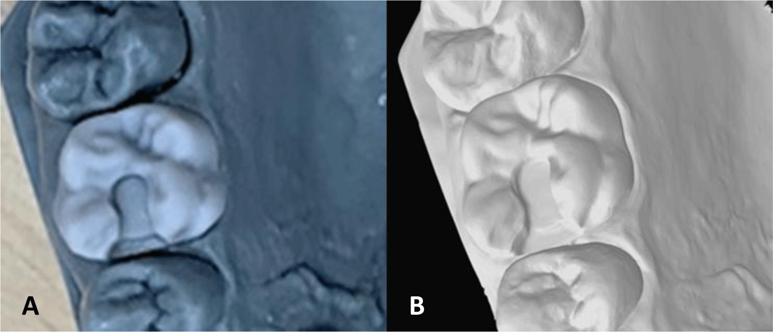
In this study, we used Mimics Research software (Materialize N.V, version 21.0, Technologielaan 15, 3001 Leuven, Belgium) to design the inlay cavity in maxillary left first molars following the guideline of Ahlers M. et al (2.5mm occlusal-isthmus width, 1.5mm occlusal depth at the central pit, 1mm proximal box height)[7]. Maxillary first molar was chosen because the maxilla is less concerned with saliva problem than the mandible, which made this in vitro research more similar to the clinical setting. This teeth model was then 3D printed 3 times, followed by modifying the depth of proximal box of each tooth. The proximal boxes of 2mm and 3mm were prepared using a flat-end tapered diamond bur (TF11, Mani Inc., Japan). The depth of these cavities is controlled and measured using a periodontal probe. Each tooth was in turn mounted onto the maxillary model before being scanned. To mimic the intra-oral environment, the model was fixed in a dental phantom head during the scanning procedure.
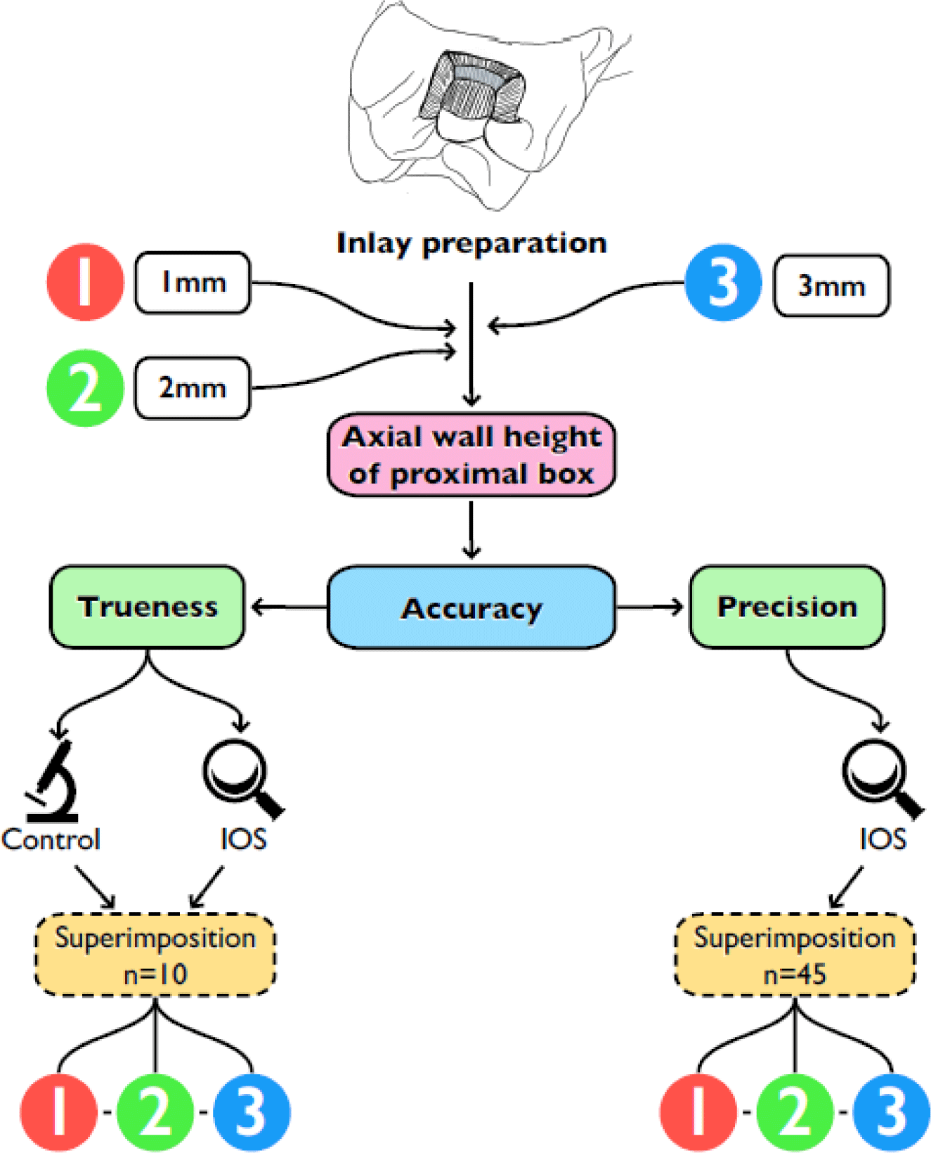
Ten digital impressions of each prepared tooth obtained by Medit i700 IOS (Medit Corp., Korea) were used as experimental scan files. Scanning was conducted by an experienced operator with at least 2-year experience of using intra-oral scanners and at least 20 clinical cases using intra-oral scanners. The scanning was started from the distal side of tooth 27 and then proceeded mesially to the mesial side of tooth 14 following manufacturer’s recommendation. To acquire the highest resolution in the inlay cavity, we re-scanned tooth 26 with the HD mode. Details that are scanned insufficiently would appear as holes and be indicated by arrows by the scanning software. The scanning process was completed considering all surfaces of the prepared cavity was recorded with no holes visible on the screen. As the process ended, the files were saved and the Process Data (As it is) option minimize the distance between surfaces on different scans. All 11 scans of each set were trimmed at the same time so that the surface areas of all scans getting analyzed would be similar. Next, the irrelevant areas were deleted, leaving only the inlay cavities to be evaluated and compared later.
The accuracy of the digital impressions was assessed via trueness and precision, based on definition 5725-1 of the International Organization for Standardization. Trueness refers to the closeness of agreement between the experimental and the reference results, while precision refers to the closeness of agreement among the experimental results obtained under the same condition. Each and every experimental scan file in 1 set was superimposed with the reference file and the difference between each pair was noted to evaluate the trueness (n=10). The precision was evaluated by the difference of the experimental was selected before post-processing to keep only the original scanning data and avoid auto-correction from the software. To get the reference data, teeth containing inlay cavity were removed from the maxillary model, powder coated and scanned by an industrial scanner (C500 scanner, Medit Corp., Korea). The powder sprayed on the teeth following manufacturer’s instructions before scanning was standardized powder with micro-thin particles that allowed the scanner to read the surface accurately. This scanner was operated under following conditions: 92x70x60mm scanning volume, field of view (FOV): 120mm, point spacing: 0.056mm, accuracy: 0.01μm, resolution: 2.0 MP.
All of the scan files including the experimental and reference ones were exported in standard tessellation language (STL) format. In preparation for the superimposing process, scanning data were distributed into 3 sets according to 3 heights of 1, 2, and 3mm with each set containing the reference scan file and 10 experimental scan files. As shown in Figure 2.
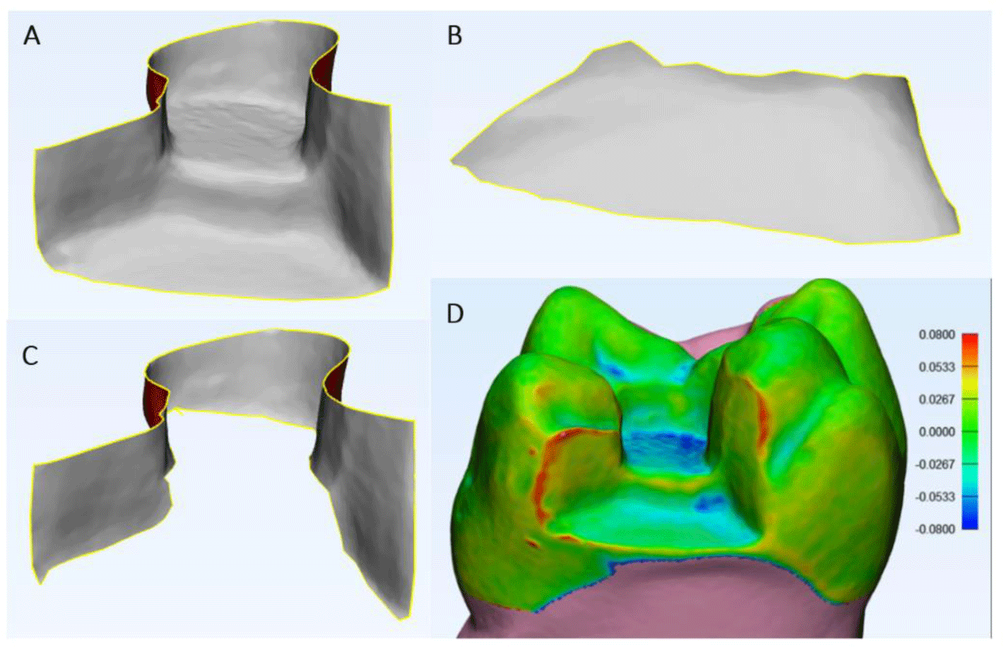
The digital models were analyzed using the 3D superimposition software, 3-Matic Research (Materialize N.V, version 13.0, Technologielaan 15, 3001 Leuven, Belgium) to measure the deviation. Firstly, the experimental and reference files were aligned using the N-points Registration tool on the software by minimizing the distance between 3 manually selected points on both files. The models then got trimmed so that only the teeth 26 remained and got aligned again with the Global Registration tool which did the superimposition automatically to scan files from each other (n=45). Each superimposed scan file is evaluated in 2 areas: the buccal-lingual (BL) and the gingival area (fig 3B, 3C). The mean, minimum and maximum deviations were used to quantify the difference between pairs. A color-coded map is shown on the software to indicate the distribution of the deviation of the surfaces with red referring to inward deviation (positive range) and blue referring to the outward deviation (negative range) of the experimental scan, hence the statistics were assessed separately in the negative and positive ranges. A low deviation indicated high trueness or precision. Considering deviations >-50μm and <50μm for clinical acceptability[8, 9], the ratio of elements <-50μm to total elements in the negative range and the ratio of elements >50μm to total elements in the positive range were calculated and analyzed. As shown in Figure 3.
Statistical analysis was performed using JASP (version 0.16, University of Amsterdam, The Netherlands) and GraphPad Prism 9 (version 9.3.0, GraphPad Software Inc, USA). The data are expressed as mean ± standard deviation (SD) or median and interquartile range. Normality was checked by the Shapiro Wilk (n = 10) and Kolmogorov-Smirnov (n = 45) tests, and variance equivalence was checked by Levene’s test. Using one-way ANOVA and Tukey’s post-test, we compared data with normal distribution and equal variances between groups. Data with a normal distribution but unequal variances were compared using the Brown Forsyth/Welch one-way ANOVA and Dunnett’s T3 post hoc test. We compared non-normally distributed data using the Kruskal-Wallis test and Dunn’s post hoc test. P-values of <0.05 were considered statistically significant.
3. RESULTS
Outcome variables for value of trueness were mean average deviation (mm), minimum/maximum average deviation (mm) and unacceptable/total elements distribution ratio (%). Generally, the superimposition result indicated the outward deviation in gingival wall and inward deviation in buccal-lingual wall. This research only dug into buccal-lingual and gingival wall since “depth” was the main factor taken into consideration, pulpal and axial walls remained untouched throughout the preparation procedure, so they were considered the same in all 3 groups. The results of the experimental scanner and the reference are compared in detail below in Table 1. In both areas, the results showed that the 1mm group had the best trueness while the 3mm group presented the lowest trueness, regarding mean and minimum/maximum average deviation values. Considering the deviations of 50μm as clinical acceptability, the analysis elucidated the percentage of unaccepted deviated area which is presented by in Figure 4D. Regarding gingival wall, all 3 groups showed less than 3% area of deviated further acceptable range with the 1mm group presented the least percentage. Similarly, in buccal-lingual wall, the 1mm group showed the least proportion of unacceptable elements, while the 2mm group showed the highest with about 3.492%. In this study, we used the scan files by industrial 3D scanner as the reference.
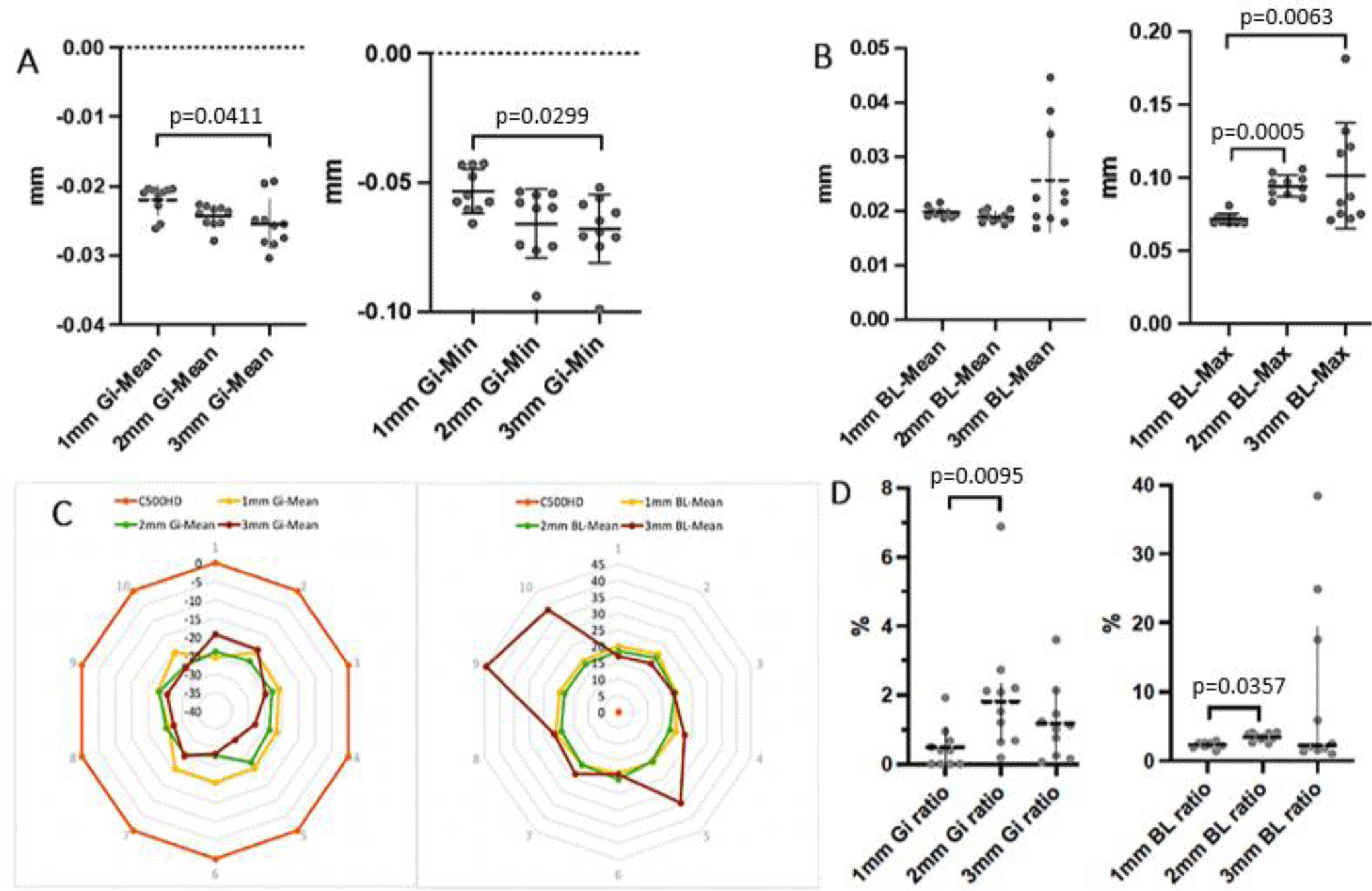
The gingival area was evaluated in negative range since there were no positive elements. The mean negative average deviation values showed that the 1mm group (-0.02095mm) had the least deviation, followed by 2mm (-0.0238mm) and 3mm (-0.0256mm) groups. The 1mm group also significantly showed the best value among the 3 groups in regard to mean minimum deviation value -0.0534mm. However, the values between the 2mm and 3mm groups showed no significant difference - 0.06601mm and -0.06784mm respectively. As for the ratio of clinically unacceptable to total elements in 3 groups, the 1mm (0.397 [0-0.74]%) group showed the lowest proportion, the 2mm group (1.809 [0.669-2.337]%) showed a significantly higher percentage than the 1mm group, the 3mm group (1.066 [0.214-1.622]%) had the higher proportion than 1mm group but there was no significant difference.
As for the BL area, only the positive range was assessed since there were no negative elements. The mean average deviation values of the 1mm, 2mm, and 3mm groups were 0.0196 mm, 0.0188mm, and 0.02205mm respectively and showed no significant deviation. The 1mm showed the significantly lowest mean maximum deviation value 0.0707mm, the 2mm and 3mm groups’ values were 0.09475mm and 0.08485mm respectively. The clinically unacceptable total ratio of the 1mm group (2.41 [2.062-2.62]%) was significantly lower than the 2mm group (3.492 [3.018-4.066]%), and 3mm group (2.275 [1.481-19.4]%) had no significant difference with the other 2 groups.
Figure 4 shows the color-coded maps created for assessing the distribution of deviation patterns with respect to trueness. The majority of deviations occur in the gingival wall of the cavity.
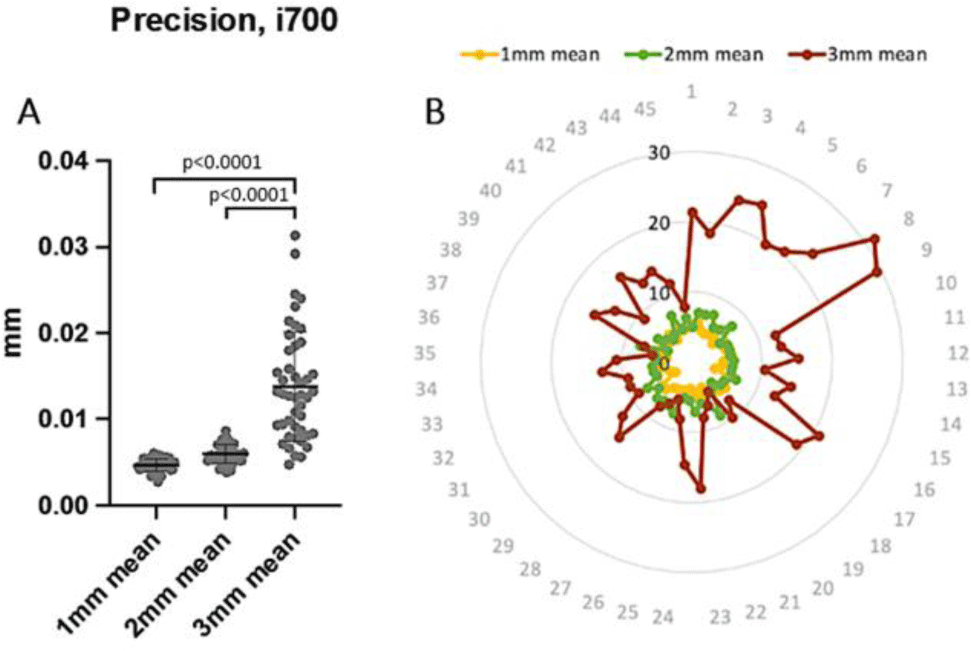
Outcome variables of value of precision was mean average deviation (mm). Precision including the mean average and mean maximum deviation values of 45 scan files of each group is shown in Table 2. Regarding mean average deviation, the 3mm group (0.01377mm) had the significantly highest deviation among all groups, while the 1mm group (0.0047mm) and 2mm group (0.005971mm) showed no significant difference from each other.
| 1mm group | 2mm group | 3mm group | |
|---|---|---|---|
| Mean (mm) | 0.004696± 0.0007113 | 0.005971± 0.001093 | 0.01377± 0.006372 |
In summary, the 1mm group had the highest precision, followed by the 2mm group, with no statistical difference. Meanwhile, the 3mm group with the greatest proximal box had a higher potential than the others to generate impression image scattering (Figure 5).
4. DISCUSSION
This study is the first research including the latest version of 3D-in-motion video technology IOS Medit i700 to investigate the accuracy of digital impressions of inlays with different cavity depths. Study of Kim et al (2021) have shown that the depth of the inlay cavity affects the quality of the digital impression. especially in the position of the cavity borders [6]. In general, the deeper the cavity, the less accurate the impression [6]. However, this study only compared 2 different groups (1mm and 2mm) with Primescan scanner (Dentsply Sirona). The IOS accuracy depends on many factors, of which the focal length of the scanner is an important one. Our study focused on one type of scanner (Medit i700) with 3 different cavity depths, from which the research results can be used to recommend clinicians about the limitation of cavity depth in order to get the most accurate results. In this study, we prepared the sample by designing and 3D printing simultaneously. This method helped to unify the cavity design between the samples. Particularly, increasing the cavity depths with a high-speed handpiece helped to simulate the process to the clinical setting as much as possible. The teeth were attached firmly to the jaw model with safety locks, ensuring the similar conditions firmness in the stable model, so that the scan for experimental data would also be simulated with clinical settings. The tooth then got separated from the jaw and scanned to obtain reference data, this eliminated interference factors such as gingival and adjacent teeth to make scanning more convenient and accurate. In addition, the sample was also powder coated and scanned with the Solutionix C500 industrial scanner with an optimal resolution (5μm - according to the manufacturer’s reported data), ensuring maximum accuracy of the reference data. All experimental scanning procedures were performed on the phantom according to the manufacturer’s instructions as in clinical practice. However, this method had a limitation was that it did not completely simulate other clinical challenges, especially lip and tongue movements and saliva flow.
During data analysis, to evaluate the influence of cavity depth, we focused on analyzing the cavity rather than the entire surface of the scanned teeth. The gingival and buccal-lingual wall were analyzed separately. The separate analysis was what differentiated this study from other studies using digital superimposition, demonstrating better the influence of cavity depth through specific area elements on the digital impression accuracy.
The results highlighted that the accuracy of Medit i700 IOS was evidently affected by different cavity depths. More specifically, the deeper the cavity was, the worse the IOS accuracy became. Regarding trueness, the assessment of the cavity was divided into 2 areas: the gingival wall (Gi) and the buccal-lingual wall (BL). Dividing into 2 main areas would help to accurately assess the gingival area (positive results) without being affected by negative results at the BL area. The same was true for the BL region also as the results here could be independently evaluated and not influenced by the positive results in the gingival region. Furthermore, when assessing the effect of inlay cavity depth on the accuracy of digital impression, the evaluation of the buccal and lingual walls may be affected by the flare and undercut of these two walls. Therefore, the division of 2 independent regions for evaluation was necessary. In general, the superimposition results showed that the gingival wall of the experimental data were located higher than that of the reference (more to the occlusal plane), showing negative values (blue) in the superimposition color-coded map. Meanwhile, the BL walls were more flared buccally and lingually, especially in the cavity borders, showing positive values (red) in the color-coded map. This had the potential to affect the accuracy of CAD-CAM restorations: a gap at the gingival finish line, thicker cement gap than designed, and unfit inlays due to larger size at the buccal and lingual walls.
Quantitative analysis of deviation showed that the deeper the cavity, the lower the trueness of the gingival wall. However, there was only a statistically significant difference between 1mm and 3mm groups. The mean average deviation values of the gingival wall trueness of 3 groups were within the clinically acceptable threshold (50μm) [8, 10, 11]. This value was similar to the trueness of high-quality scanners such as Primescan and Trios4 - proven in many studies [12, 13]. Hence, Medit i700 scanner was capable of scanning cavities up to 3mm deep with high trueness. However, the trueness value of the 3mm group was statistically significantly lower than that of the 1mm group with higher data scattering. Considering the mean minimum deviation value (Gi min) of the gingival wall, the research results showed that the 3mm group had the minimum deviation of about -70μm, while the 1mm group limited this value to about -50μm. This suggested a higher risk of creating a gap between inlay and tooth on the gingival wall in the 3mm group compared with the 2mm and 1mm groups. The intraoral scanner’s ability to scan deep cavities is directly affected by the camera’s focal length. Medit scanning software allows clinicians to adjust the scan depth. Therefore, in order to improve the trueness of the digital impressions of deep cavities, it is recommended that the clinician increase the value of the scan depth to ensure accuracy. In this study, we used the default mode (18.5mm) on all 3 groups for an overall view. The improvement of inlay cavity accuracy by adjusting the scan depth would require further investigation.
The BL walls were mainly distributed with positive values (yellow and red), negative value positions (blue) had almost no distribution in this region. The analysis results after superimposition showed that the mean average and maximum deviation values and data scattering of the BL walls in the 3mm group were higher than that in the 2mm and 1mm groups. However, these values were all within the clinically acceptable threshold. The deviation values in the BL wall were greatest in the 3mm and 2mm groups. These values were statistically significantly higher than the 1mm group. Many other studies also recorded differences in the BL walls of cavity [14, 15]. This deviation may be due to limitations in the scanning angle, and obstructions such as adjacent teeth and gums that obstruct the light from the scanner to the cavity surface [16-18]. In addition, rotating the scanner in the posterior teeth area was limited, making it difficult for light to reach the entire surface of the outer and inner walls. In addition, the divergence of the BL walls may also be responsible for the lower light absorption of the BL walls.
Precision shows the agreement or repeatability of the scanned data. The more repeatable the scan data, the better the error control and deviation compensation. Specifically, during the design process, the technician can reduce the cement gap on the gingival wall and increase on the BL walls to ensure a tight fit of the inlay. However, to estimate this compensation, the scan data of a given scanner system needs to have good precision. In this study, the precision results at each depth were evaluated by means of the deviation after superimposition. The results showed that the 3mm group had significantly higher scattering than the 1mm and 2mm groups. This showed that as the depth of the inlay cavity increased, the repeatability of the scan data tended to decrease. This could again be explained by the light acquisition from the scanner being affected by cavity depth. As a result, the pixels received by the camera have a certain bias, these deviations are concentrated in hidden areas such as edges and transition angles.
Conclusion
The study was conducted to evaluate the accuracy of digital impressions in different depths. The research results can partly be evidence to make recommendations on inlay depth for CAD/CAM technique, as well as can serve as a reference for other studies of similar or larger scale in the future. Within the limitations of this study, the results showed that Medit i700 was able to scan inlay cavities with depth of 1mm and 2mm with high accuracy (20-30μm). However, the accuracy (especially the precision) is significantly reduced in the 3mm cavity. To ameliorate this problem, clinicians could perform a variety of methods such as resin composite cavity elevation prior to scanning or altering the depth of field scanning in the high-depth cavities. However, the effectiveness of these methods needs to be studied further. Furthermore, further studies regarding repeating independent experiments to verify the results and increased sample size should be conducted for better understanding in this area.